

Industries · 8 min read
Georeferencing drone detections from a box in the frame to a GPS point the crew can drive to
Heading, altitude and field of view turn a boxed insulator into a coordinate. The log and the video disagree on time, and a re-planned flight moves every box.
Summary
This post takes a detection in a drone frame, a cracked insulator or a solar panel, and turns it into a coordinate a line crew can drive to, using the aircraft's position, heading and altitude and the camera's field of view. It concludes that the maths is the easy part and that timing between the flight log and the video, duplicate markers across frames, and a re-planned flight are where the coordinates go wrong. It is for utility inspection and survey teams.
Andreas Ohrvall · CTO · Sep 25, 2026
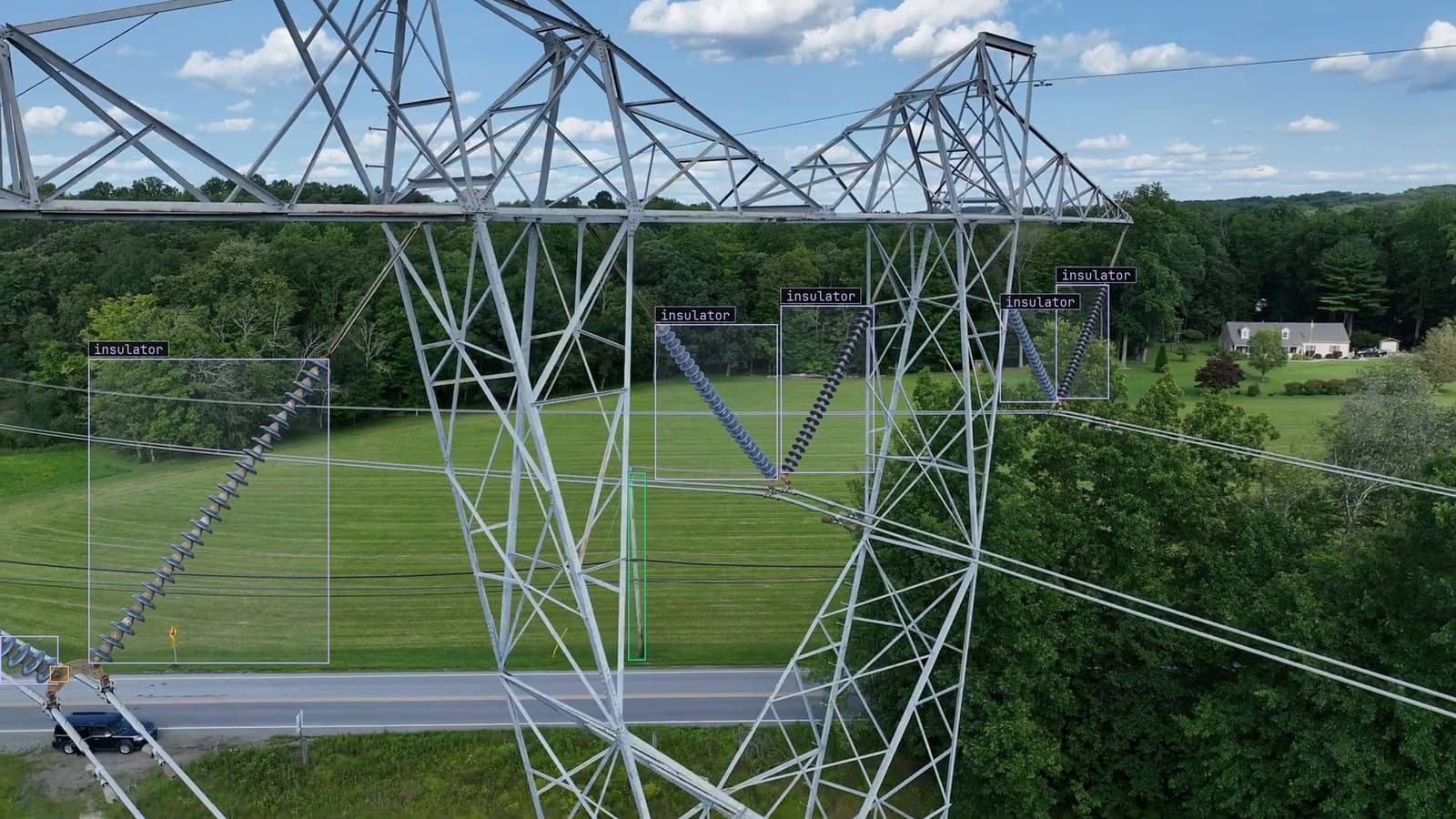
Transmission tower over a country road with insulator strings and a corrosion mark boxed, from a customer inspection run
The drone comes back from a morning along the corridor with an hour of video and a model has drawn boxes on it: a cracked insulator on one frame, a corrosion mark on another, a tree crown too close to the conductor on a third. The line crew looking at the boxes on Monday has a question the frame cannot answer. Which tower. A box at some pixel position in a frame from a flight over a corridor of identical towers is a fact about the video, and the crew needs a fact about the ground.
Turning the one into the other is arithmetic, and the arithmetic is the part of this that goes right. The part that goes wrong is everything the arithmetic assumes.
Object detection gives a pixel and the flight log gives everything else
The model's output is a box in the frame with a class: insulator, cracked insulator, corrosion, vegetation. That is object detection doing its job, and the frames it was trained on came from the same corridor at the same altitude the pilot flies for coverage, because a tower on a different approach is a different image. What the box lacks is a position on the Earth, and the position comes from four numbers the box never sees.
Three of them are in the flight log for every moment of the flight: where the aircraft was, which way it was pointing, and how high above the ground it was. The fourth is a property of the camera rather than the flight: how wide a slice of the world the lens takes in. With those four, a pixel anywhere in the frame can be projected onto the ground and given a latitude and longitude.
The flight log has to actually carry all three. A subtitle file muxed into the video often has position and a timestamp and nothing about heading, and without heading there is no way to say which direction the top of the frame points. A full telemetry export from the flight controller, sampled at a fixed interval, is the source that works.
The maths is a footprint, an offset and a bearing
For a camera pointed straight down, the width of ground the frame covers is set by the altitude and the lens. The wider the field of view and the higher the aircraft, the more ground per frame. Divide that width by the frame's width in pixels and every pixel is worth a known distance on the ground, sideways; the same with the frame's height, for distance forward and back. A box's centre is some number of pixels from the frame's centre, so it is some number of metres from the point directly under the aircraft, sideways and forward.
Those two offsets become a distance and a bearing. The distance is the straight line through the two offsets. The bearing is the aircraft's compass heading plus the angle of the offset within the frame, since the frame's "forward" is wherever the aircraft was pointing. From the aircraft's position, that distance along that bearing gives the coordinate, and a constant-bearing calculation on the Earth's surface does the last step.
All of it assumes the camera is pointed straight down. Tilt the gimbal and the frame's footprint is a trapezoid rather than a rectangle. A pixel near the top of the frame is worth far more ground than one near the bottom, and the simple arithmetic is wrong by an amount that grows with the tilt. Flights meant for georeferenced detections are planned with the gimbal locked down. Oblique passes, which are often the better ones for seeing an insulator, get a more involved projection or a different job.
The log and the video do not agree about time
The flight log samples the aircraft's state at a fixed interval and the video records frames at a much higher rate, so several frames share one log entry, and the aircraft moved between them. That is jitter, and it puts the same insulator at slightly different coordinates on consecutive frames.
The larger error is the offset between the two clocks. The log spans the whole flight, from the pad at 9 am through transit to landing, and the video is one segment of it. Matching the first frame of the video to the right moment in the log is the step that, done wrong, puts every marker a hundred metres down the corridor from where it belongs. The log usually marks when recording was on, and the first contiguous block of recording entries is the video. A flight with three videos has three blocks, and the log has to be split so each video is paired with its own.
Check it visually before trusting anything. Plot the flight path, the ground footprint of the video, and the markers on a map. Markers inside the footprint along the path mean the pairing is right. Markers in a neat line a hundred metres off mean the clocks are misaligned. Markers scattered everywhere mean the heading is missing.
One insulator across forty frames is one marker
The model boxes the cracked insulator on every frame it appears in, and a pass over a tower at survey speed puts the same insulator in dozens of frames. Georeferenced one at a time, that is dozens of markers in a cluster a few metres wide, and the crew's map is a smear. Merging markers within a written distance of one another, a few metres for an insulator, into one marker at their average position gives the crew one point per defect.
A marker that appears in a single frame is more likely a false detection than a defect, since a real insulator persists as the aircraft passes. Suppressing markers seen in fewer than two frames cleans the map further, at the cost of anything at the very edge of the pass. What survives is a map with a point per defect and the frames behind each point, and the crew drives to the point.
Across our energy work, 21,000+ hazard detections per month come out of models like the one drawing these boxes, and the ones that lead to a truck being sent are the ones that made it onto a map.
An aside from the corridor. The crew still carries the printed tower schedule with the tower numbers on it, and the first thing they do with a georeferenced marker is read off which tower it is nearest. A tower number is what the work order system understands and a coordinate is not.
A re-planned flight moves every box
The airspace changes, or the weather, or the battery, and the pilot flies the corridor at a different altitude on a different heading. The insulators have not moved. The scale they arrive at in the frame has, and so has the angle. The model that was fitted to the old altitude boxes fewer of them, and the ones it boxes are at a pixel scale the arithmetic handles fine while the model does not. The drift catalog calls this a camera moved, and on a drone it is the commonest event there is, because every flight is a chance to re-plan.
LexData takes the corridor model through its whole life. You type what to look for, Lexi puts a box on every insulator in every frame, and a person checks each label before anything trains on it. The model then runs on the footage the flights bring back, in the cloud or on your servers, and frames it is unsure of come back to a person. The corrections retrain it, and the new version replaces the old one with no downtime. After a re-planned flight the doubted frames are the whole flight, and the reviewer's corrections on a short window of them are what the next version learns the new altitude from.
The signal is the correction rate stepping up on the first flight at the new plan, and it is cheaper to catch on the review screen than on the crew's map.
My own view, as the person who has to make the pipeline hold together end to end, is that the flight plan should be a field on every frame from the moment the footage lands, altitude and heading and gimbal angle beside the timestamp. Every failure in this post is a failure to know which flight a frame came from. The predictive maintenance on grid assets use case needs the same thing for a different reason: a rate is the same quantity measured twice, and two flights are only comparable once they have been registered to the asset.
See it on your own footage.
Start with your footageMore in Industries
Industries · 7 min read
Counting the screws in a kit with object detection over the bench
A camera over the kitting bench counts every screw and bottle one box at a time. Exact for kits, a band for cases, and a half-hidden item is a written rule.
Rajiya Sultana · Sep 25, 2026
Industries · 7 min read
Automated water meter reading with a camera in the vault
Ten digit classes in a fixed row turn a truck roll into a frame. A rolling digit and condensation on the glass are the frames that come back to a person.
Stephen Biswas · Sep 25, 2026
Industries · 7 min read
Body-in-white inspection with a station camera on unpainted steel
Dents on a bare body shell hide in the reflections. Masks give the extent, a second pass decides reportable, and a tightened tolerance is a spec change.
Finn Ellingwood · Sep 25, 2026