

Operations · 6 min read
Object measurement with computer vision, turning pixels into millimetres without a calibrated camera
A tile of known size on the belt gives each frame its scale. A rotated box follows the fillet, a polygon follows its edge, and a nudged camera breaks the plane.
Summary
This post explains measuring objects on a conveyor from a fixed camera without a full calibration, using a reference object in the frame for a scale factor per image, rotated boxes for parts that lie at an angle, and polygons for irregular ones. It concludes that the labels have to be as tight as the measurement needs and that a moved camera silently breaks the flat-plane assumption the scale factor rests on. It is for the people grading or sorting parts by size on a line.
Sheikh Srijon · GTM Lead · Oct 1, 2026
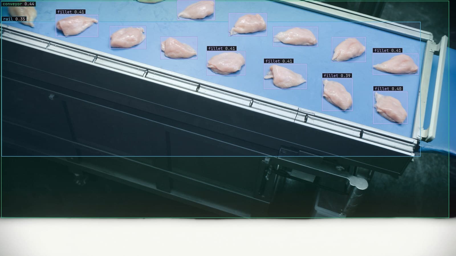
Fillets on a blue conveyor at a food processing line, generated scene with detections from our model
The grader on fillet line 2 sorts by length. At 6 am the operator checks it with a steel ruler that lives taped to the rail beside the belt: a fillet from the small chute, a fillet from the large chute, the ruler across each, the numbers on a whiteboard. The grader itself was set up by a contractor two years ago and nobody at the plant knows what it measures with.
A camera over the belt can do the ruler's job on every fillet, and it does not need to know the lens's focal length to do it. It needs one thing of known size in the frame.
A reference object in the frame gives each image its own scale
The belt on line 2 is flat, the camera looks straight down at it, and every fillet lies on the same plane. Under those conditions, the number of pixels per millimetre is the same everywhere on the belt, and it can be read off anything in the frame whose size is known. A printed tile glued to the belt's edge, a bar with two marks a hand's width apart, the belt's own width if it is known.
The model finds the tile, measures it in pixels, and the ratio to its real size is the scale factor for that frame. Every other measurement in the frame is pixels times that factor. If the belt is raised a finger's width for cleaning and put back slightly higher, the tile looks bigger and the factor changes with it, which is the whole reason to keep the tile in shot rather than measure the scale once at commissioning.
My own view is that the tile should be permanent, in shot, on every station that measures anything, because a scale factor measured once is a scale factor that goes wrong quietly.
An axis-aligned bounding box measures the wrong thing at an angle
The obvious first approach is to detect each fillet with a bounding box and read the box's width and height as length and width. It works for fillets lying square to the belt. It fails for every fillet that lies at an angle, and on line 2 most of them do, because they come off the trimming station however they fall.
A fillet at forty-five degrees fills a box that is wider and taller than the fillet is. The bounding box measures the fillet's shadow on the belt's axes rather than the fillet. The longer and thinner the object, the worse the error, and a grader that sorts on that number puts long fillets in the large chute for lying straight and in the small chute for lying diagonally.
A rotated box follows the fillet and a polygon follows its edge
The fix for angle on line 2 is a rotated box: the same four corners, allowed to turn with the object, so its long side lies along the fillet and its short side across it. Length is the long side, width is the short side, and the angle comes for free, which is what a downstream robot at the packing station wants anyway.
The fix for shape is a polygon. A fillet is not a rectangle at any angle. It tapers, it curves, and a rotated box around it still includes belt at the corners. A polygon traced along the edge gives the area and the longest chord, and the belt is excluded. For a grader that pays by weight and estimates weight from area, the polygon is the label that makes the estimate honest. The surface defect detection use case makes the same argument for a scratch: only a mask carries the length, and disposition is a size call.
The choice is about what the station needs. Rotated boxes are faster to label and to run. Polygons are the right shape for irregular parts and the wrong effort for square ones.
Labels have to be as tight as the measurement
A measurement inherits every loose edge in its training labels. A box drawn 2 px wide of the fillet on every frame is not noise that averages away. It is a fixed offset that every measurement carries, multiplied by the scale factor into millimetres, for as long as that version runs.
So the labeling on line 2 is done with the ruler in mind. You type "fillet" and "tile", Lexi proposes a rotated box or a polygon on every frame, and a person checks each one before anything trains on it, with the reviewer's attention on the edges rather than on whether the fillet was found. Finding it is easy. Drawing its edge to the pixel is the job, and it is why labels come back checked at up to 99.9% accuracy rather than proposed and trusted.
A moved camera breaks the plane the scale rests on
The whole method rests on the belt being a flat plane seen square on, so that one scale factor holds everywhere. Tilt the camera and it stops being true. The far end of the belt is now further from the lens than the near end, and a fillet at the far end measures short. The tile at the belt's edge gives a factor that is right for its own corner and wrong for the middle.
The drift catalog calls this a camera moved, and the story is always the same: a wash-down, a bracket re-tensioned, a housing replaced, and nothing reported, because the feed looks fine to a person. The signal is the operator's whiteboard. The ruler and the camera part company in one direction from one date, on one station, while line 1 is unchanged.
LexData takes the fillet model through its whole life. You type what to look for, Lexi puts a box on every frame, and a person checks each label before anything trains on it. The model then watches the line 2 camera, in the cloud, on your servers, or on a runner beside the recorder. Frames it is unsure of come back to a person, the corrections retrain it, and the new version replaces the old one with no downtime. After the wash-down, the doubted frames from line 2 are the ones where the fillets sit where the model has weak evidence, and the correction rate on that camera is the first thing to move.
The ruler stays taped to the rail. Once a shift, a fillet from each chute, and the number goes on the whiteboard next to the camera's.
See it on your own footage.
Start with your footageMore in Operations
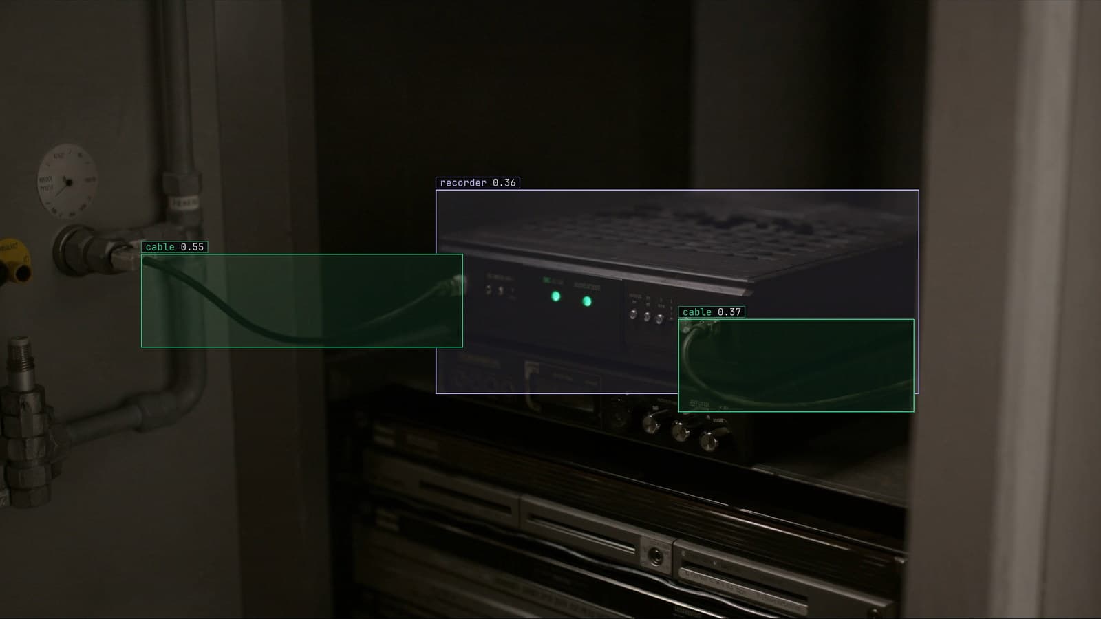
Operations · 7 min read
AGPL-3.0 licensing risk for computer vision teams serving a model
A camera streaming to a served detector is the network interaction the licence was written for. What a legal review will ask, and why to pick the weights first.
Ayman Quadir · Oct 1, 2026
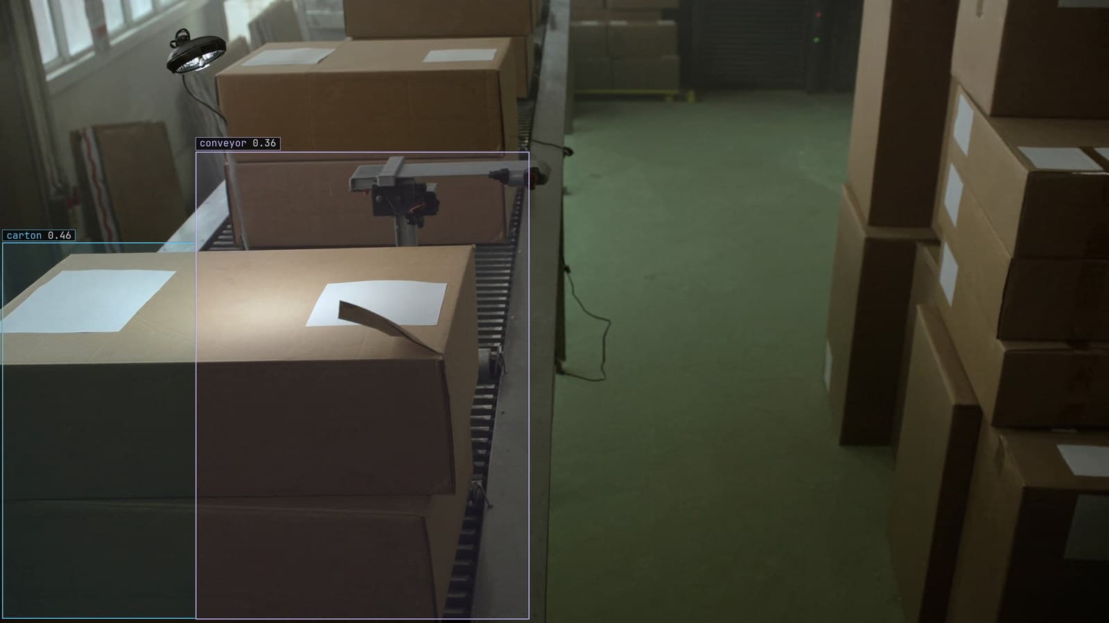
Operations · 7 min read
Cloud vs owned GPU inference for computer vision, worked out per camera hour
A plant on three shifts and a retailer with cameras spread across stores get different answers from one sum, and footage leaving the building is a cost too.
Ayman Quadir · Oct 1, 2026
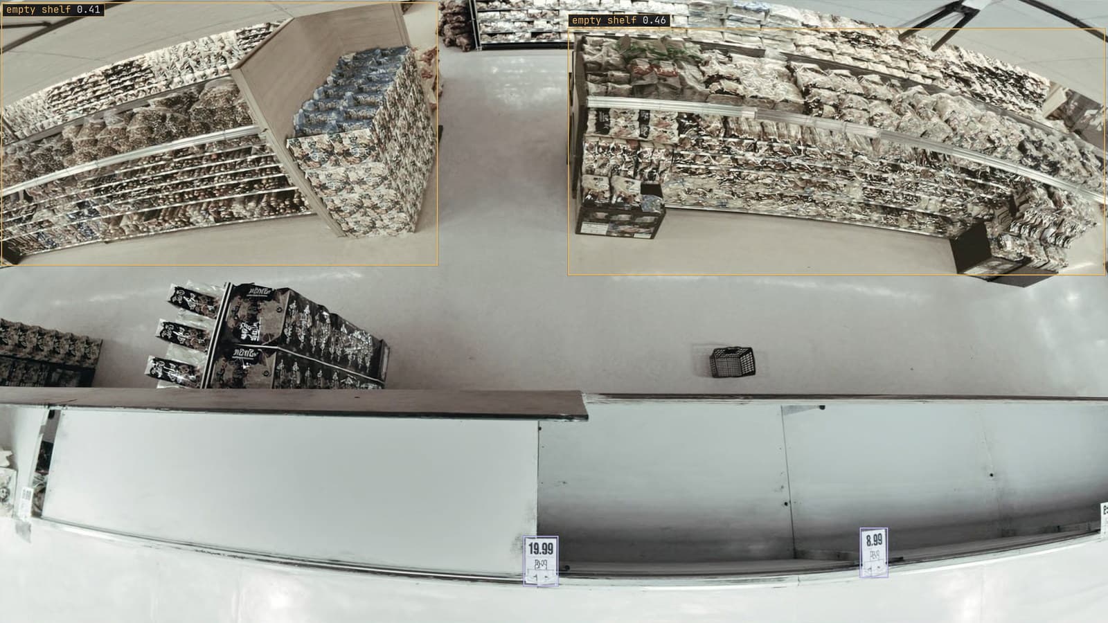
Operations · 7 min read
Computer vision heatmaps drawn from the aisle cameras a store already has
Footpoints from every tracked box, aggregated over a day and mapped onto the floor plan, show where footfall goes. A camera nudged in cleaning shifts the map.
Rajiya Sultana · Oct 1, 2026