

Operations · 6 min read
What SCADA is and where a camera fits in it
Sensors, PLCs, a network, a server and a historian, and a camera's detection entering the stack as one more tag beside pressure and flow.
Summary
This post explains SCADA layer by layer, from the sensor on a transformer to the historian in the control room, using one substation as the running example. It then shows where a camera's detection enters that stack, as a tag written through a webhook into the broker the SCADA layer already reads. It is for operations and controls people who are being asked what a camera would add to a system that already works.
Sheikh Srijon · GTM Lead · Sep 23, 2026
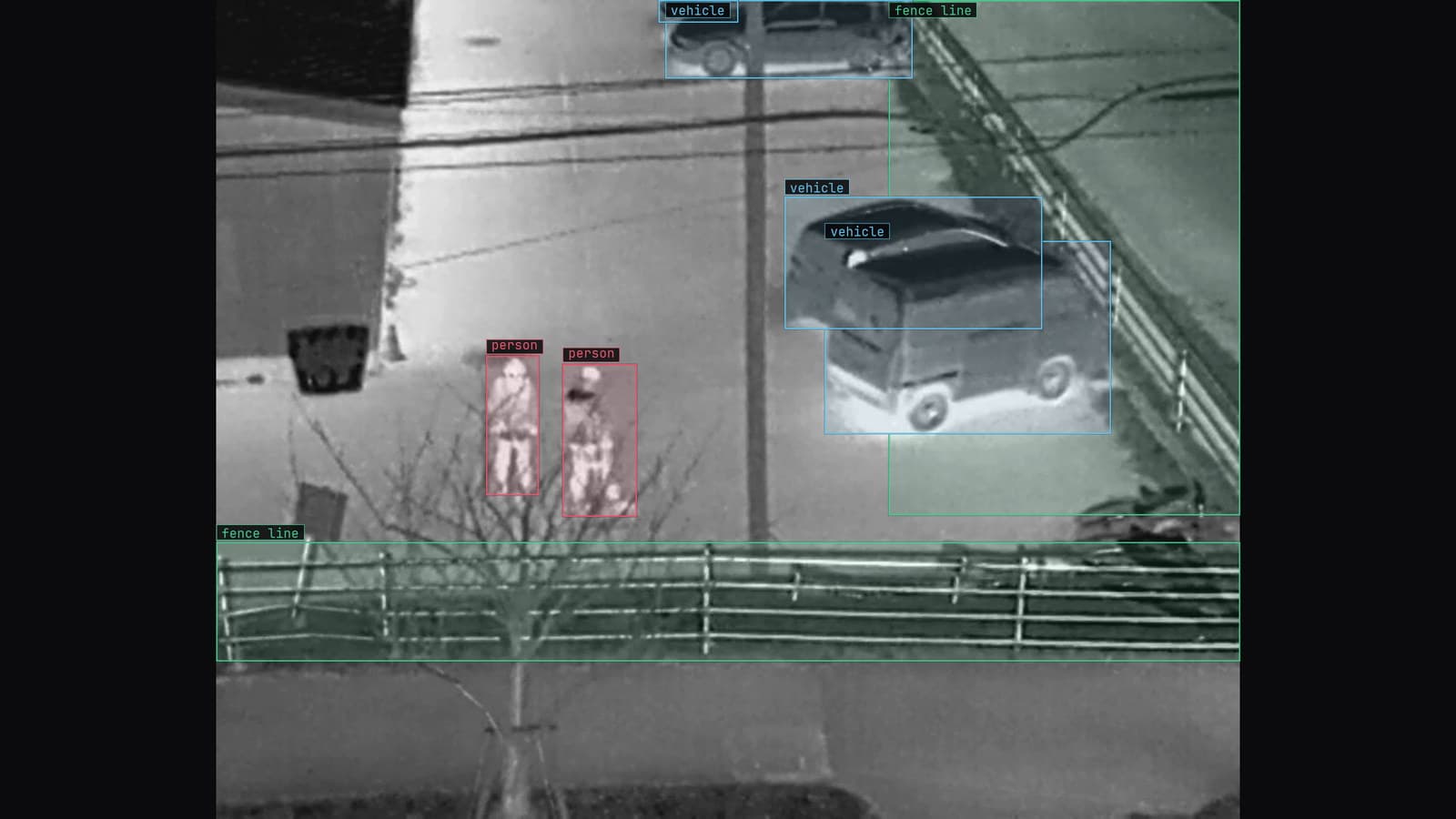
Thermal camera on a site fence line at night, two people at the fence and vehicles boxed, from a customer site camera
At 3 am the transformer in bay 2 of a rural substation is running a few degrees warmer than its neighbour. Nobody is there. A thermocouple on the tank reports the temperature to a cabinet in the yard, and the cabinet reports it to a server in a control room forty miles away. An operator on the night desk sees the number turn from green to amber on a screen drawn to look like the yard. That chain, from the thermocouple to the amber tile, is SCADA.
The acronym expands to supervisory control and data acquisition, which describes it accurately and tells you nothing. What it does is read the plant and, when told to, write back to it.
Sensors and actuators are where SCADA touches the equipment
The bottom of the stack is physical. In bay 2 that means temperature probes on the transformer tank, a pressure transducer on the gas-insulated switchgear, a flow meter on the cooling loop, a position contact on each breaker. Each one turns something in the world into a voltage or a current on a wire. Going the other way, an actuator turns a command into a motion: the breaker trips, the cooling fan starts, the tap changer steps.
None of these devices knows what a substation is. The thermocouple reports millivolts. The meaning is added one layer up.
PLCs and RTUs give the voltage a name
The cabinet in the yard holds a remote terminal unit, or at a plant a programmable logic controller. Either one reads the wires, scales the millivolts into degrees, and gives the value a name the rest of the system will use, something like BAY2_TX_TEMP. It also holds the local logic that must work when the control room is unreachable: if the tank temperature crosses a limit, start the fans, whether or not anybody upstream is listening.
That local logic is the part of the system people forget when they imagine it as a dashboard. The RTU in bay 2 will trip the fan at 3 am on its own. The control room finds out afterwards.
The network carries named values to a server and historian
The named values travel over a network that was often laid decades before the internet reached the site. Serial lines and radio links still carry a good share of the world's substations, and the protocols on them are old and plain. Modbus, still everywhere, was published in 1979 and is essentially a way to ask a device for the contents of a register.
At the top, a supervisory server collects the values from every RTU it owns and presents them on the HMI, the human machine interface, which is the screen drawn to look like the yard. Beside the server runs the historian, which stores every value against a timestamp for as long as the utility keeps records. The historian is the quiet half of the system. The HMI tells the night desk what is happening; the historian tells an engineer in six months what happened, and when, and what else moved at the same time.
A camera enters SCADA as a tag beside pressure
A camera on the fence line of bay 2 is a sensor with an awkward output. Where the thermocouple produces a number, the camera produces a frame, and the control room has no tile for a frame. What it has a tile for is a tag, so the job is to turn what the model sees into a named value the server already knows how to hold.
That is what an alert is. In LexAlert a rule is written as a sentence, with a severity and a cooldown, approved before it goes live: a person inside the fence at bay 2 outside working hours, critical, to the on-call channel. The same rule delivers to a webhook, and the webhook lands in the broker the control room server already reads. The detection arrives as BAY2_FENCE_PERSON with a timestamp, a tag like any other, beside BAY2_TX_TEMP and the breaker positions, on the same HMI and in the same historian. The monitoring and alerts guide covers the webhook; the tag naming is the utility's own.
The substation and equipment monitoring use case is built on this shape: a hot bushing and an intruder are both position questions on a fixed camera, and both reduce to a tag. On the energy sites we run, the same alert path produces 21,000+ hazard detections per month across grid assets, and every one of them is a row somebody can query.
The tag serves the screen and the frame serves people
A tag is enough for the HMI. It is not enough for the operator deciding whether to send a crew forty miles at 3 am. So the alert carries the frame with the box drawn on it to the on-call channel while the tag goes to the server. The operator judges from the picture in one glance whether the person at the fence is a linesman who forgot to sign in or somebody with bolt cutters.
My view, and it is a view about historians rather than cameras, is that the historian is where a camera earns its keep. The alert at 3 am is dramatic and rare. The row that says the fence detection at bay 2 coincided with a temperature rise on the same night, three months later when an engineer is investigating a fault, is what a scalar sensor could never have provided.
LexData takes the substation model through its whole life. You type what to look for, Lexi puts a box on every frame, and a person checks each label before anything trains on it. The model then watches the cameras the utility already has, in the cloud, on its servers, or on a runner beside the recorder. Frames it is unsure of come back to a person, the corrections retrain it, and the new version replaces the old one with no downtime.
The operator's override on a false alarm is the correction. An owl on the fence at night, called a person once, comes back for review and the next version has seen an owl.
The air gap is mostly a story on the diagram
Utilities describe their control network as air-gapped, and a few genuinely are. Most have a historian that engineering can query from the office network, a vendor VPN for the RTU firmware, and a laptop that has been plugged into both sides. The honest question when adding a camera is where the model runs and what leaves the site. The answer that suits a control network is a runner beside the recorder, on the utility's own network, with the alert firing locally first and only doubted frames leaving for review.
Written that way, the camera adds one more tag and one more client to a network that already has hundreds of each. The night desk sees an amber tile for the fence at bay 2 next to the amber tile for the transformer, and the historian keeps both.
See it on your own footage.
Start with your footageMore in Operations
Operations · 6 min read
Turning a detection into an OPC UA tag the PLC can read
A count, a presence flag and a confidence value as OPC UA variables, written on change from the alert webhook, while the reject decision stays with the PLC.
Stephen Biswas · Sep 23, 2026
Operations · 7 min read
Integrating machine vision with PLC, SCADA, MES and ERP systems
A cracked weld is a bit for the PLC, a thumbnail for the HMI, a record for the MES and a yield figure for the ERP. Shape it once, beside the recorder.
Andreas Ohrvall · Sep 23, 2026
Operations · 7 min read
Getting a defect detection to the PLC over MQTT
One webhook from the alert into the plant's broker, a topic per line and camera, and the PLC and the SCADA screen subscribe like any other client.
Andreas Ohrvall · Sep 23, 2026