

Operations · 6 min read
Camera calibration for computer vision, and why the part at the edge of the frame measures wrong
A straight edge bows at the corner of the frame, so a part that passes in the centre fails at the edge. Calibrate once, and again the day the lens changes.
Summary
This post explains camera calibration for an inspection station, from the barrel distortion that makes an edge part fail tolerance to the intrinsics measured once with a printed target and the hand-eye calibration an arm needs. It concludes that a swapped camera or lens is the day calibration has to be redone, and that the model cannot tell you it happened. It is for manufacturing engineers putting a camera over a line.
Stephen Biswas · Engineer · Sep 30, 2026
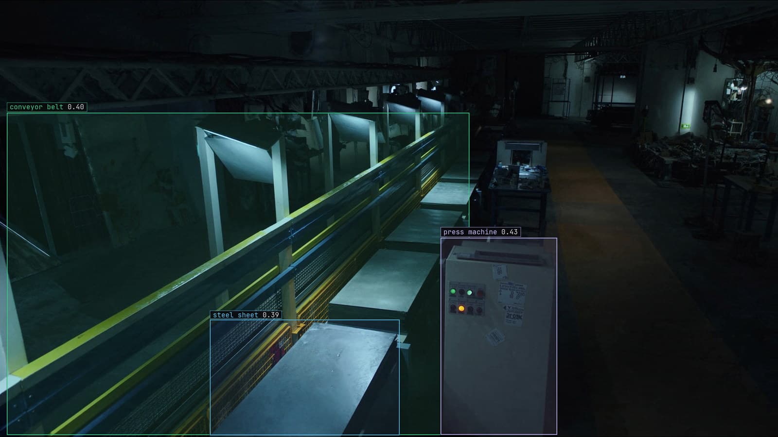
Steel panels on a stamping line passing an inspection station, generated scene with detections from our model
The bracket that comes off press 2 has a slot that must sit within half a millimetre of the drawing. The camera over the outfeed conveyor measures the slot on every part, and for the parts that pass through the middle of the frame the measurement agrees with the gauge on the bench. The parts that ride the left edge of the belt fail, one in every few, and when the inspector picks one up and puts it on the gauge it is fine.
The part is not wrong. The picture of it is.
A straight edge bows at the corner of the frame
Every lens bends the world a little, and a wide one bends it a lot. A straight edge that crosses the centre of the frame stays straight; the same edge near the corner curves outward, the way a barrel bulges. The slot on a bracket at the left edge of the belt from press 2 is drawn on the sensor slightly stretched, and a measurement in pixels that was right in the centre is wrong there.
To an inspector watching the monitor the frame looks fine, because people do not measure with their eyes. The model does. It counts pixels between two edges, and the pixels at the corner do not mean what the pixels in the middle mean.
Intrinsics and distortion are measured once with a printed target
Calibration is the fix, and it is a measurement of the camera rather than of the parts. A printed grid of known squares is held in front of the lens in perhaps 20 frames, tilted and shifted so it visits every corner of the image. From where the corners of the squares land, the camera's own numbers are solved: the focal length, the point on the sensor the lens is centred on, and the coefficients that describe how the bowing grows towards the edges.
Those numbers are the intrinsics. They belong to this camera with this lens at this focus, and they do not change when the part changes or the belt speeds up. Once they are known every frame is straightened before anything measures it, and the slot on the bracket at the left edge measures what the gauge says.
The grid printed on the office printer curls within a day, and a curled target gives a calibration that is subtly wrong in a way nobody can see. The stations that get this right print the target once and mount it on something flat.
Object detection finds the part, calibration decides what the box means
The model over press 2 does a detection job first. It finds each bracket on the belt, puts a box on it, and finds the slot inside the box. The surface defect detection use case works the same way: the detector finds the thing, and what the finding means, a pass or a fail, a millimetre or two, is decided by what the frame's pixels are worth in the world.
Object detection on its own is indifferent to distortion. A bracket at the edge of the frame is still a bracket, and the box still lands on it. Calibration matters at the next step, when the box is turned into a size. This is why a station can show a good detection rate for a month while the measurements it produces at the edges are wrong every day. The 99%+ accuracy maintained in production on our manufacturing work is a detection figure; the measurement behind it depends on a calibration someone did with a flat target and did again when the camera changed.
The arm that keeps missing needs a second calibration
A robot cell off the end of the same line picks brackets from tray 1 and the arm misses one in a batch by a few millimetres, always in the same direction. The camera over the tray is calibrated, the model finds the bracket, and the coordinates it reports are right in the camera's frame. The arm lives in a different frame, and nobody has told the two frames where they are relative to each other.
Hand-eye calibration is that conversation. The arm moves a target to known positions, the camera sees it in each, and the transform between the camera's world and the arm's world is solved. It is a separate measurement from the intrinsics, and it is the one that shifts when a cable pulls the camera bracket or the arm's base is re-bolted after a service. A consistent miss in one direction is the signature.
A swapped camera or lens is the day to redo it
The camera over press 2 fails on a Thursday and the maintenance crew fits the spare, same mount, same position, a lens from the same drawer. The frame on the monitor looks the same. The intrinsics are not, because no two lenses bow the image the same way, and the calibration file written for the old one straightens the new frame wrongly from the first part.
The drift catalog calls this a camera was replaced, and the clue is the shape of the change: an abrupt step on one camera from the exact date of the swap, while the neighbouring stations are unchanged. The model's boxes still land. The measurements at the edges move.
My own view is that a calibration target should be mounted on the wall beside every inspection station, so that a swap is followed by a calibration on the same shift rather than a ticket that waits until someone notices the failures. It is a ten-minute job with the target to hand and an afternoon of arguments without it.
LexData takes the bracket model through its whole life. You type what to look for, Lexi puts a box on every frame, and a person checks each label before anything trains on it. The model then watches the outfeed camera, in the cloud, on your servers, or on a runner beside the recorder. Frames it is unsure of come back to a person, the corrections retrain it, and the new version replaces the old one with no downtime. After the swap, the doubted frames from press 2 arrive with the new lens's character in them, and the correction rate on that one camera is the signal that the calibration file is older than the camera.
The bench gauge stays the reference
The inspector on the outfeed of press 2 keeps the bench gauge. Once a shift a bracket from the left edge of the belt goes on it, and the number is written next to the camera's number. When the two agree the calibration is holding. When they part, in one direction, from one date, the camera has changed and the parts have not, and the target comes off the wall.
See it on your own footage.
Start with your footageMore in Operations
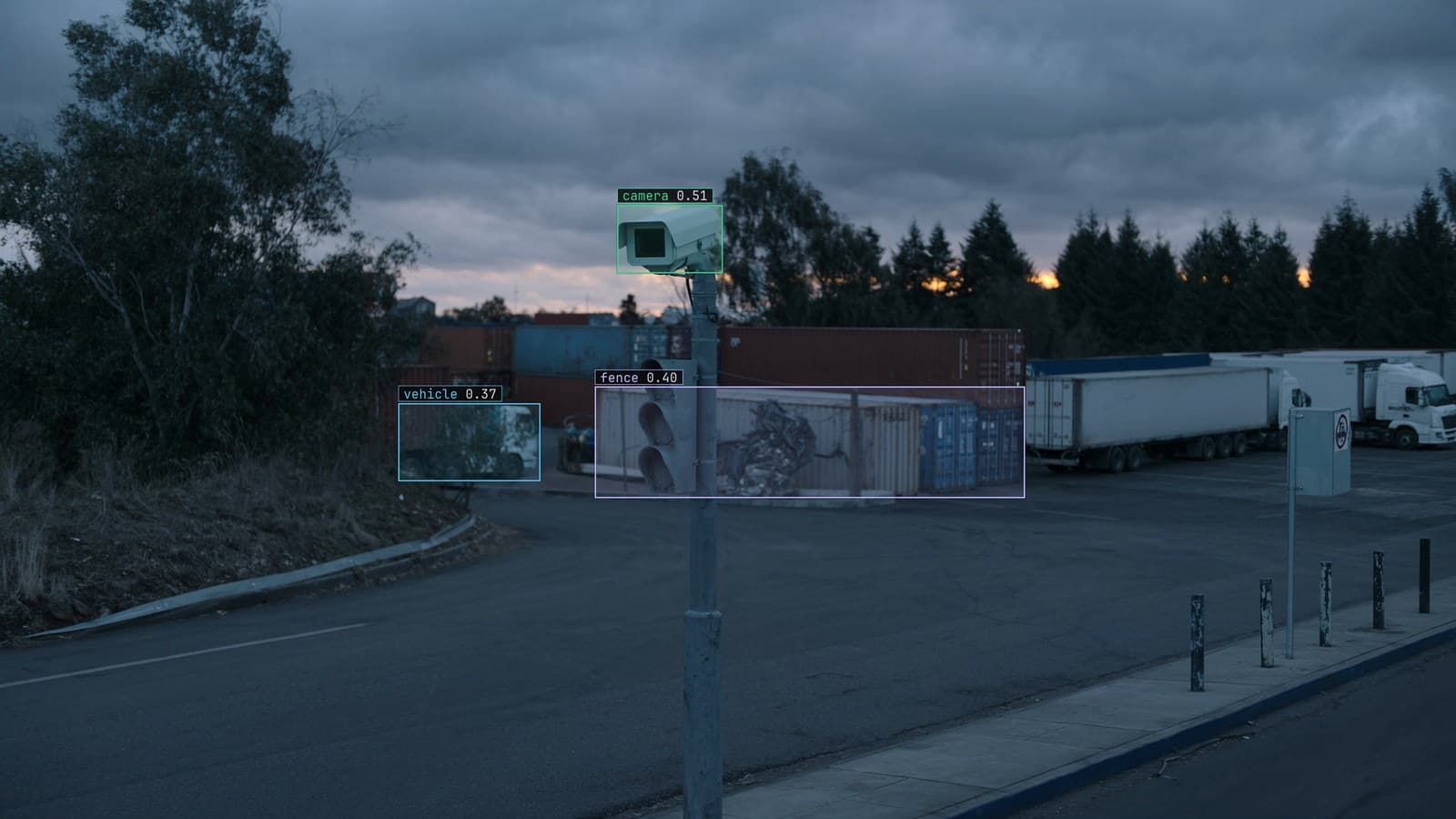
Operations · 6 min read
Evaluating a computer vision platform once the pilot ends
The feature spreadsheet cannot tell you which platform survives the second year. Walk the lifecycle instead, from import to a retrain that keeps the old frames.
Ayman Quadir · Sep 30, 2026
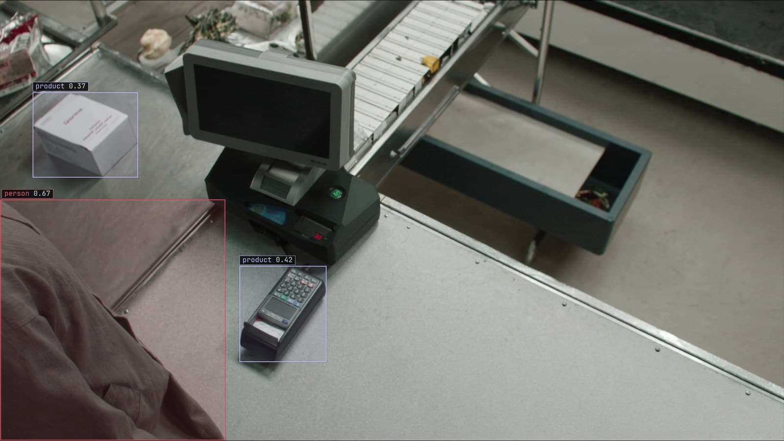
Operations · 6 min read
Face blurring for privacy in computer vision, done before the frame is stored
A blur applied after the request arrives is a blur applied to a frame that has already been copied. The step belongs at ingestion, beside the recorder.
Esdras Ntuyenabo · Sep 30, 2026
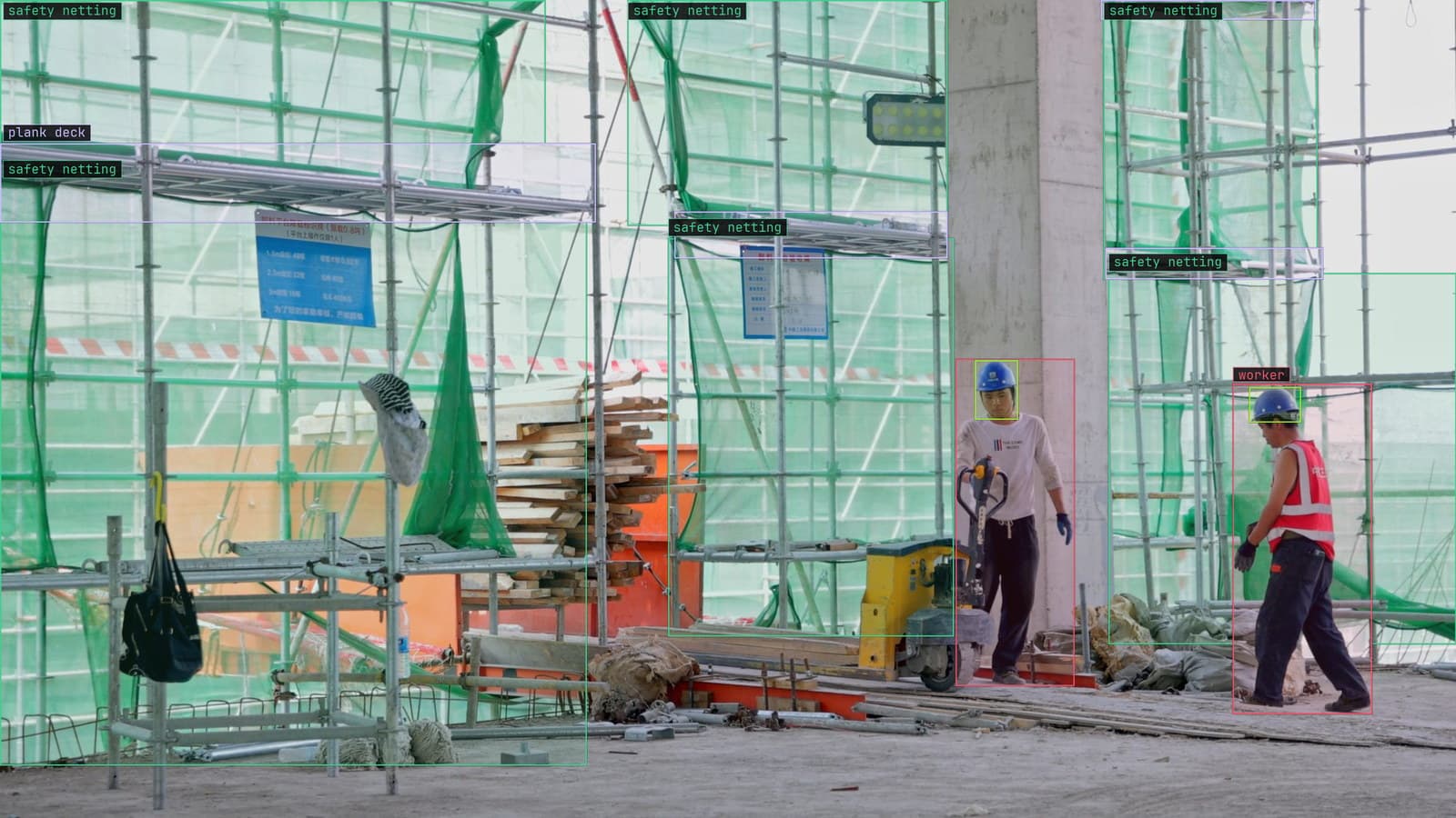
Operations · 6 min read
How to test computer vision model robustness before the weather does it for you
A vest model trained in June daylight meets October rain. Blur, darken, shift and compress the held-out frames first, and read recall per perturbation.
Rob Hickey · Sep 30, 2026